Yet Another Lift Bridge Design |
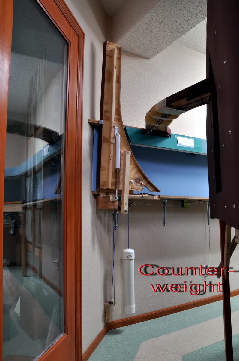
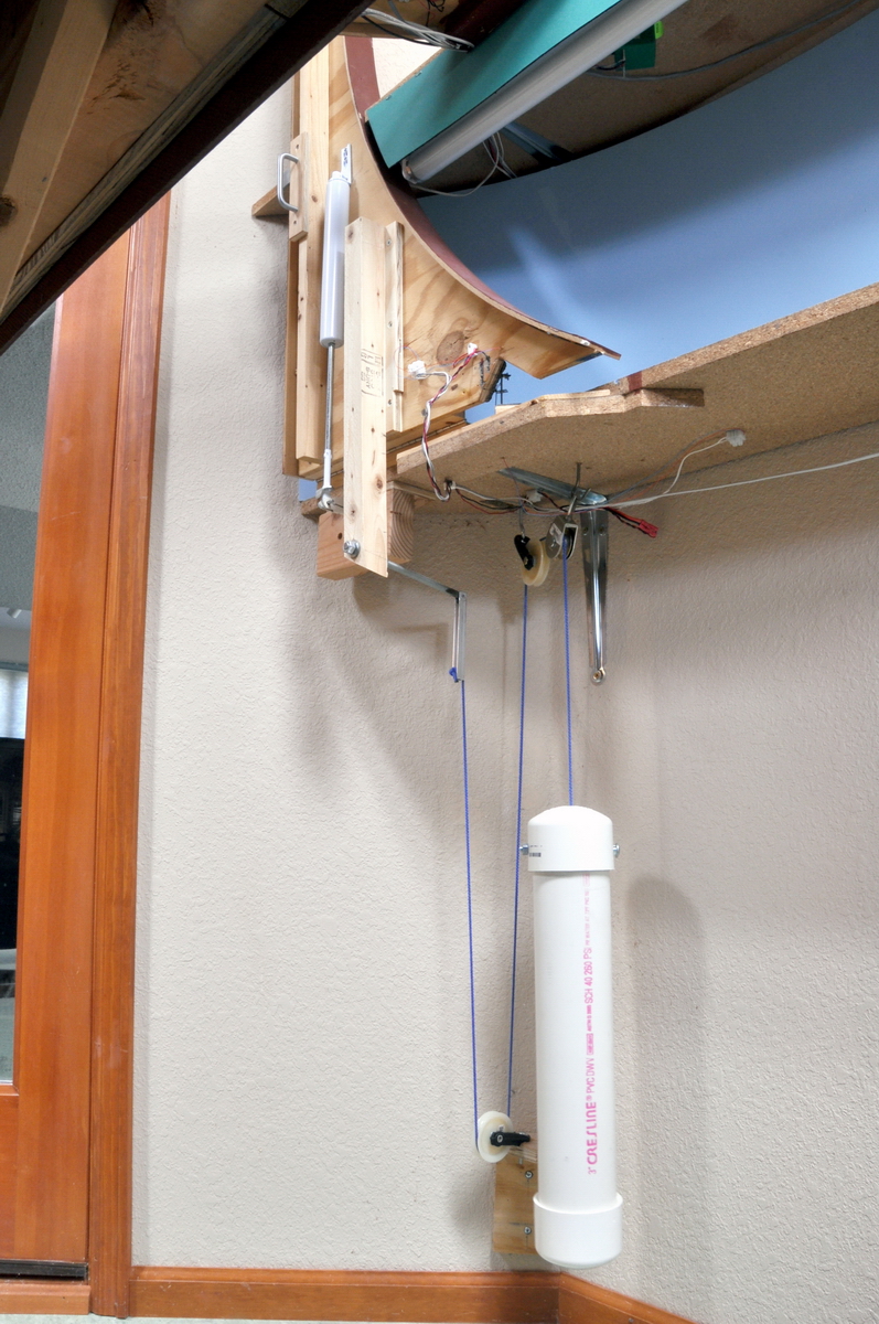
A counter-weighted lift bridge connects the lower level yard with the staging area. Both the aisle and the track crossing it have high traffic. This article describes how I automated the operation of this bridge. The first picture shows the bridge in the raised position. The bridge carries a single track that curves on to the bridge at its hinged end. A piano hinge attaches the bridge to the benchwork. The large white PVC tube acts as a counter-weight. It is attached to the lever arm with a system of pulleys. The pulleys allow the counter-weight to move straight up and down as the bridge is raised and lowered. If the weight were attached directly to the lever arm, it would swing wildly back and forth as the bridge was raised and lowered and interfere with the smooth operation of the bridge. The weight is just heavy enough to almost raise the bridge when it is closed. The geometry of the lever arm is arranged so that there is still a small force tending to close the bridge when it is completely raised. More about this later.
The closing motion of the bridge is dampened with a screen door closer. The screen door closer is the smaller white tube seen on the bottom of the bridge. This type of screen door closer is adjustable and is commonly available in hardware stores.
Click on the image for more detail. Click twice for maximum detail. Notice the threaded rod extending counter-weight attachment point back towards the wall.
|
|
|
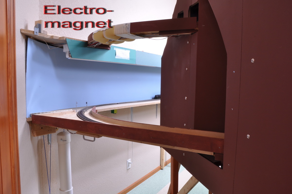
The next illustration shows the bridge in the closed position. Note the piano hinge at the left end, top surface of the bridge. The hinge is fastened to two one by twos, one on the benchwork and the other on the bridge. This raises the bridge pivot point above the level of the track work and allows the ends of the track to separate and join cleanly, with no binding or interference when the bridge is raised and lowered.
Now notice the electro magnet attached to the upper level benchwork. This magnet lines up with a steel plate fastened to the bridge deck near its middle. When the bridge is raised by someone wanting to get by, a micro switch located at the near end of the bridge opens and signals the control program (through a SMINI board) to close a relay (also through the a SMINI board) and energize the magnet. The magnet grabs the bridge with a rather satisfying click and holds it open. Also track power at the bridge ends is killed.
The bridge can be closed with fascia push buttons (located in the aisle on either side of the bridge), with a mouse click on any of the control panel monitors, or with a command from a wireless Digitrax throttle. The bridge can also be closed automatically by an approaching train. When the control program receives a command to close the bridge it opens the relay energizing the magnet and the bridge drops. A micro switch confirms that the bridge has closed properly and the control program displays the bridge status on the computer monitors. Closing the bridge also restores track power to the bridge approaches. There is a red/green LED on the bridge that warns the user not to open the bridge when a train is approaching. It the bridge is opened anyway, the computer kills all the layout power.
When the bridge control system detects an approaching train, the computer sounds a warning and kills the magnet, letting the bridge close. The train detection is done two signal blocks ahead of the bridge. If the block next to the bridge is somehow reached with the bridge open, the computer kills the power to entire layout. The computer interface to the hardware is done with custom software and CMRI boards.
Click on the image to enlarge it.
Next is a view of the bridge from underneath, showing the arrangement of pulleys that attaches the counter-weight to the bridge lever arm. Note that the threaded rod extending from the end of the lever arm projects upward through a hole in the benchwork. The reason for this is more apparent in the next illustration (showing the bridge open).
Click image for more detail
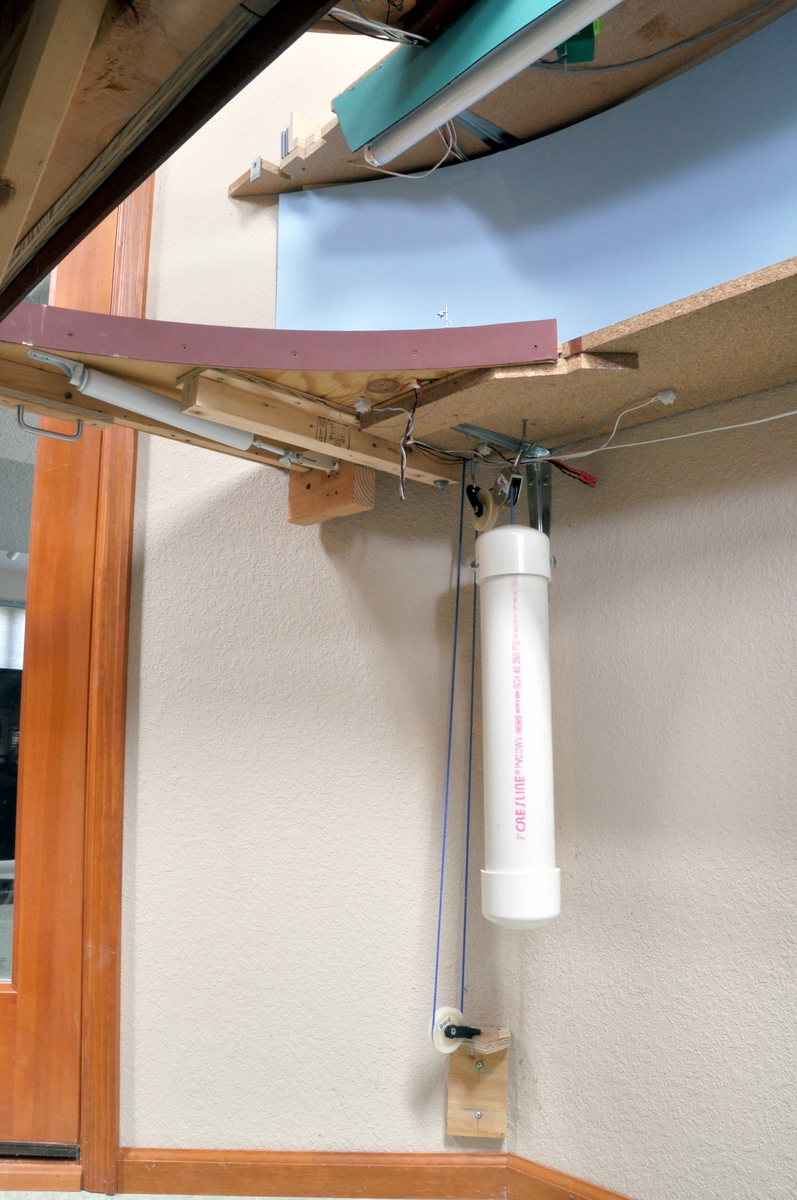
The following photo shows the bridge open. The threaded rod extending the end of the lever arm is easier to see in this photo. Note that all of the weight of the bridge is forward of the bridge pivot point (the piano hinge). This causes a fairly large force tending to close the bridge. i.e. a force pulling the end of the bridge away from the magnet and down. The threaded rod extends the end of the bridge lever arm to a point behind the pivot point. This provides just enough counter balancing force so that the bridge will close smoothly and gently and so that the electro magnet can still hold the bridge open.
When the bridge is closed, the threaded rod at the end of the lever arm extends up through the benchwork. See previous photo. Conveniently, the backdrop curves in front of the hole for the threaded rod and hides it.
Click the image for more detail.
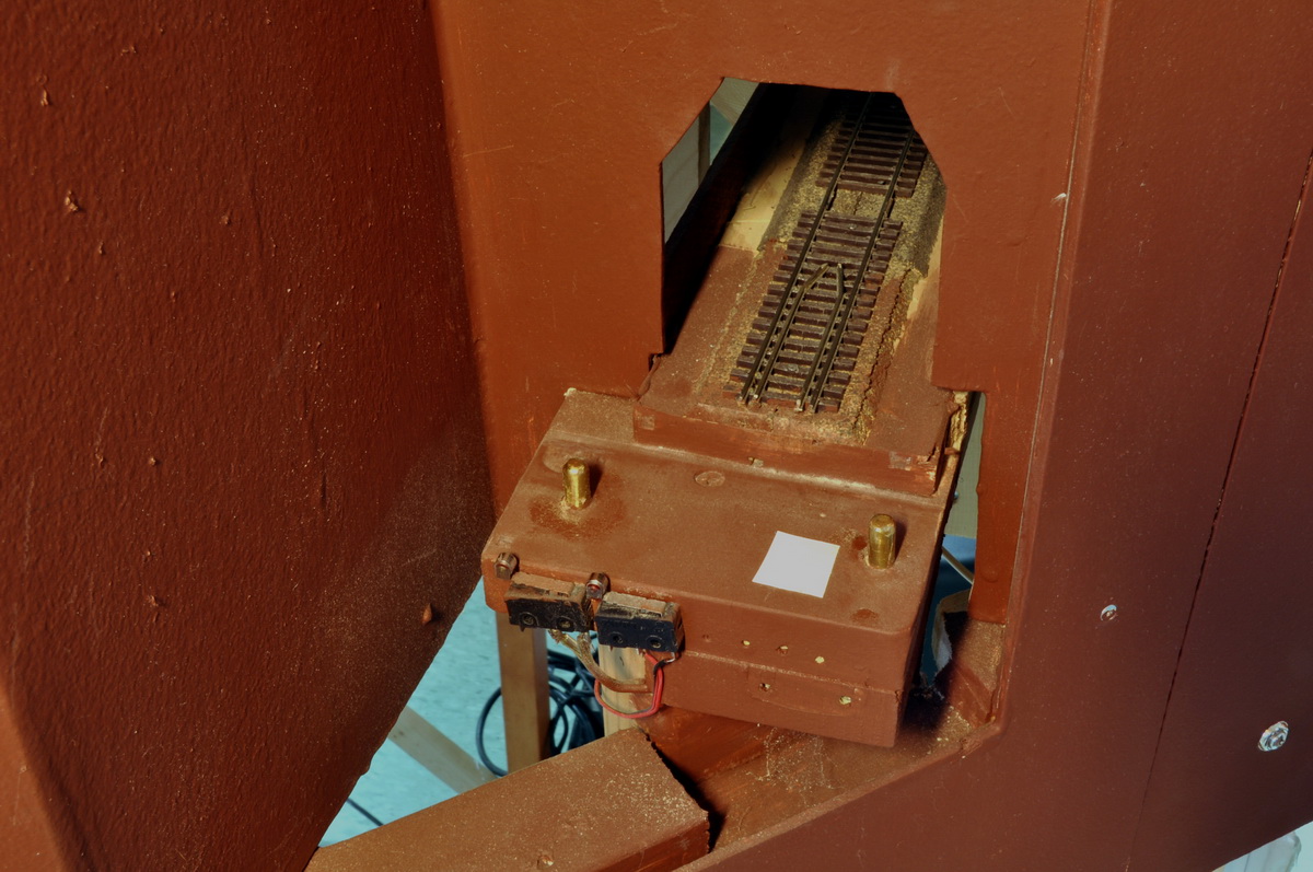
Now lets look at the other end of the bridge. The next photo shows the bridge closed. Notice that there are two holes with rounded brass pins in them. These pins locate the end of the bridge so that the track ends line up. The holes are slightly elongated to account for the change in the benchwork from summer to winter. Since Colorado is so dry, and basement is air-conditioned and somewhat humidity controlled, the seasonal change in the benchwork length at this point is only a millimeter or two. A certain amount of fiddling with this part of the bridge has been required to obtain reliable operation from season to season. But is seems to be sorted out now.
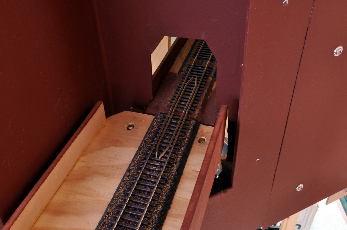
The last photo is the same shot, but with the bridge open. The brass locator pins and bridge interlock micro switches are visible. The small white square is a piece of tape used to adjust the height of the bridge end.
This may seem like a lot of trouble to go for a lift bridge, but the bridge must be unobtrusive and largely automated for layout operation to be enjoyable. This aisle must be used twice as each train climbs or descends the hill. Trains moving between the lower yard and staging must use this bridge. So the bridge gets opened and closed a lot as the layout is operated. To open the bridge, this arrangement merely requires lifting the bridge and letting the electro-magnet grab it. When a train needs the bridge, it can be closed from any command station with a mouse click, by pushing a fascia button if you are near the bridge, with a few button pushes on a wireless throttle, or an approaching train can automatically close the bridge.